Introduction to ShopBot
This article will guide you through the design of my parametric box and step by step through the process of using the ShopBot.
Having a 2D CNC milling machine leaves the FabLab with a lot of waste materials. This waste includes various types of wood with different thicknesses and dimensions. So the FabLab challenged me to make a box from the scrap wood.
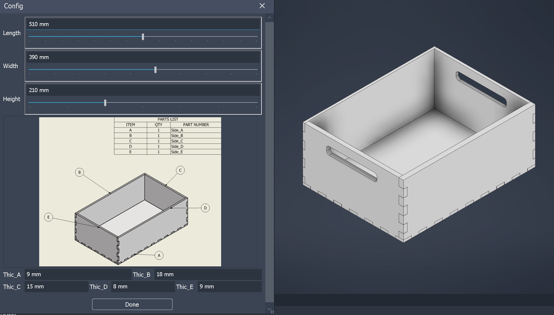
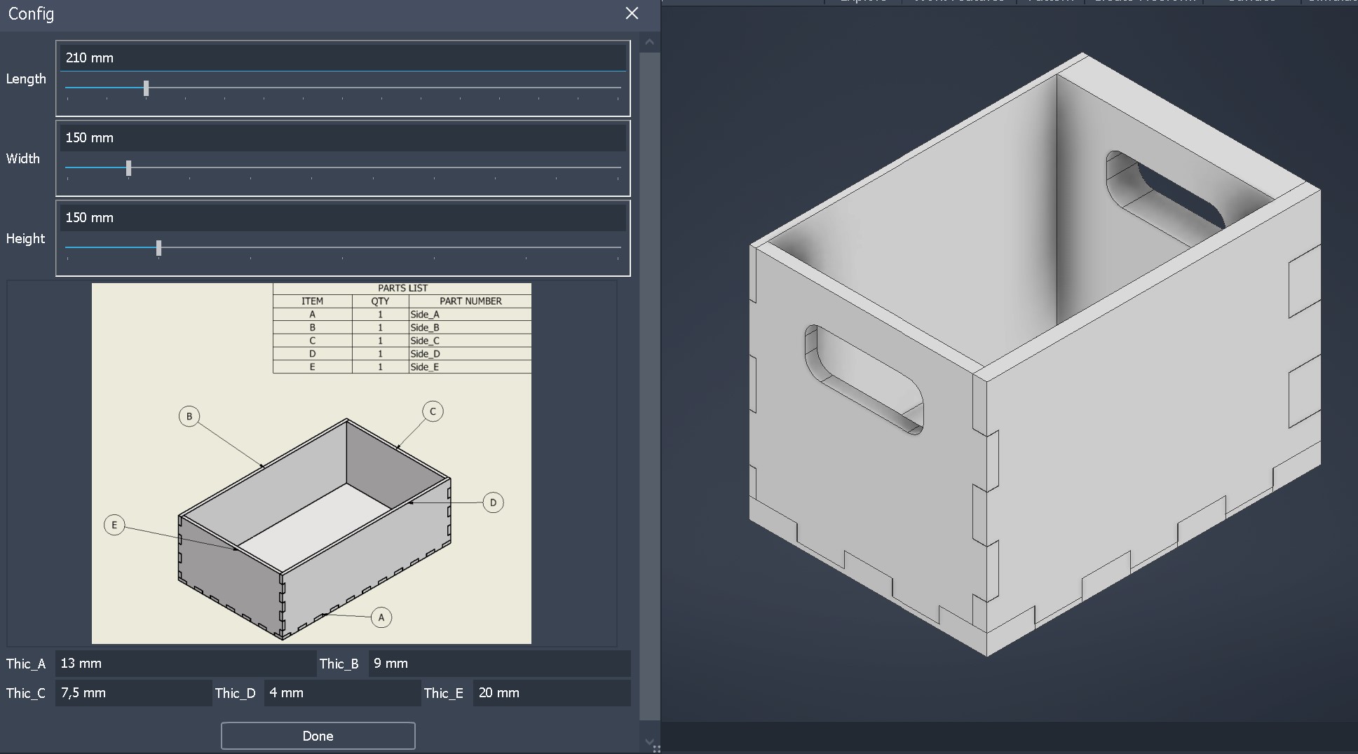
I wanted to make my box design parametric so that it can be based on any available scrap piece in the workplace. This is possible in Inventor. I gained the experience to do this in my second year of study.
Explaining how I designed the part in Inventor using iLogic is beyond the scope of this article because it could be an entire course on its own. To confirm that the box is parametric, you can refer to Figures 1 & 2.
Get your files ready
Step 1: Open VCarve Pro
- Password PC FabLab: fablab
- Open VCarve Pro 8.0 on the ShopBot PC
Step 2: Open file
In V carve it should be possible to open a lot of different files. In my case only .pdf worked. You can try what works for you.
Step 3: Specify material properties
- measure and input the length and width of your material
- meusure and input the thickness of the material
- Set the z zero (origin point) on the bottom left of the material
- Click
OK
Step 3.5: Fix drawing
Because i could only open .pdf file i had to join all vectors. You do this by typing the letter j on your keyboard and than sellecting the complete drawing.
Step 4: Create fillets
Under Edit Objects click on option Create Fillets and than in your drawing select the corners like in Figure 3.
You do this because it isn’t possible to mill 90 degree corners.
Step 5: Create drill holes
- Under
Create Vectorsclick on optionDraw Circle - Set the diameter of the circle to the diameter of your tool
- Place the circles in the corners of your material. Depending on the size of the material place circles between the corners. Do not place the circles in your drawing
Step 6: Toolpaths
In this step we create 2 toolpaths. one for the drill holes and one for the milling.
Drill Toolpath
- Under
2D View Controlclick on optionSwitch to toolpaths tab - Under
Toolpath Operationsclick on optionDrilling Toolpath - Select all the circle that were just created
- Set cutting depth to 2 mm
- Make sure the correct tool is selected
- Click on
Calculate
Milling Toolpath
- Under
Toolpath Operationsclick on optionProfile Toolpath - Select your drawing
- The
Cut Depthshould be the same as the material thickness - Make sure the correct tool is selected
Machine Vetors...should be on the Outside- Check the box for
Add tabs to toolpathand than click onEdit Tabs ... - Place the tabs like in
Figure 4, depening on the size of your drawing also place tabs in between - Click on
Calculate
Preview Toolpaths
- Under
Toolpath Operationsclick on optionPreview Toolpath - Click on
Reset Preview - Click on
Preview all Toolpaths
Now first the drill toolpath is played and than the profile toolpath. To close this window click on Close
Step 7: Save Toolpaths
- Under
Toolpath Operationsclick on optionSave Toolpath - Select the
Drill Toolpathand save it in your Folder (for exampleBox name) and give the file a clear name likeSide_A_Drill - Do the same for the
Profile Toolpath - Make sure you have 2 separete files
Working with the ShopBot
Step 1: Clear the machine
- Remove everything on the table
- Clear the space around the ShopBot
Step 2: Turn on the ShopBot
- Turn on the computer
- Turn on the Shopbot with the big red switch
- Open the ShopBot software
- Close the preview window
- Type
kfor the keypad to move the toolhead around. It’s also possible to use the arrows and use the Page up and Down keys to move the toolhead up or down
Step 3: Calibrating the ShopBot
- Make sure the correct tool is sellected, if not go to step 3.5
- Click on
Zero XYicon in the ShopBot software like inFigure 5

- Zero Z-axes
- Place the metal plate underneath the milling bit. To make sure it works first thouch the milling bit and check if number 1 input lights up green
Figure 6. - Click on
Zero Zicon in the ShopBot software like inFigure 5
- Place the metal plate underneath the milling bit. To make sure it works first thouch the milling bit and check if number 1 input lights up green
- Place your material on the bed and set the milling bit to the origin point of your material
- Zero X & Y in the ShopBot software by clicking on
[Z]eroand in the dropdown menu click onzero [2] axes (X & Y)
- Zero X & Y in the ShopBot software by clicking on
Step 3.5: Changing milling bit
- Lower the skirt of the dust extraction by unscrewing the butterfly screw till it can be lowered
- Use the 2 wrenches (one of wich is connected to the key) to unscrew the nut
- Change the bit for your tool
- Remove collet from the nut
- Match your tool diameter for the same collet diameter
- Place collet back in the nut
- Place the bit in the collet so that the bit matches the inner circle of the bit. Do this by looking from the top
- Make sure the the milling depth is 2 mm less than the protrude milling bit
- Use the 2 wrenches again to screw the nut back on
- Move the skirt back up and thighten the butterfly screw
Step 4: Machining
- Put on safety glasses and hearing protection
- Turn on the dust extractor in the back of the room by pressing the green button
- Turn on the Milling bit by turning the key on the side
When their is a problem press the spacebar on the keyboard
Drilling
- Load the Drilling toolpath in the ShopBot software
- Press
StartandOK, the ShopBot will now start drilling - When the operation is finnished turn off the milling bit by turning the key on the side
- Move the ShopBot with
kon the keyboard - Screw the material to the bed on the places the ShopBot has drilled
Milling
- Turn on the Milling bit by turning the key on the side
- Load the Milling toolpath in the ShopBot software
- Press
StartandOK, the ShopBot will now start milling - When the operation is finnished turn off the milling bit by turning the key on the side
- Unscrew your material
Step 5: Cleaning up
- Vacuum the wood chips from the bed and incase ground
- Turn off the ShopBot
- Turn off the dust extractor With the red button
- Turn off the PC
Step 6: Post-processing
Now it is time for post-processes all your parts and finnish the project.
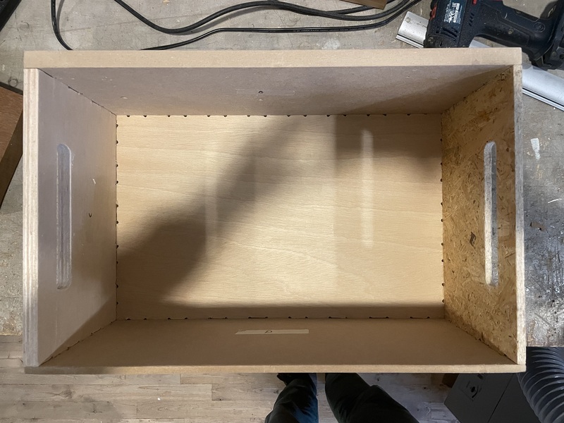
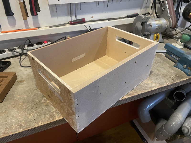
This is my end result Figure 7 & 8.