Jekyll2025-01-14T10:58:32+01:00https://projectphase.github.io/feed.xmlSven DekkerAn amazing website.Sven Dekkersven-dekker@hva.nlIntroduction to ShopBot2023-11-01T00:00:00+01:002023-11-01T00:00:00+01:00https://projectphase.github.io/documentation/introduction-to-the-shopbotThis article will guide you through the design of my parametric box and step by step through the process of using the ShopBot.
Having a 2D CNC milling machine leaves the FabLab with a lot of waste materials. This waste includes various types of wood with different thicknesses and dimensions. So the FabLab challenged me to make a box from the scrap wood.
I wanted to make my box design parametric so that it can be based on any available scrap piece in the workplace. This is possible in Inventor. I gained the experience to do this in my second year of study.
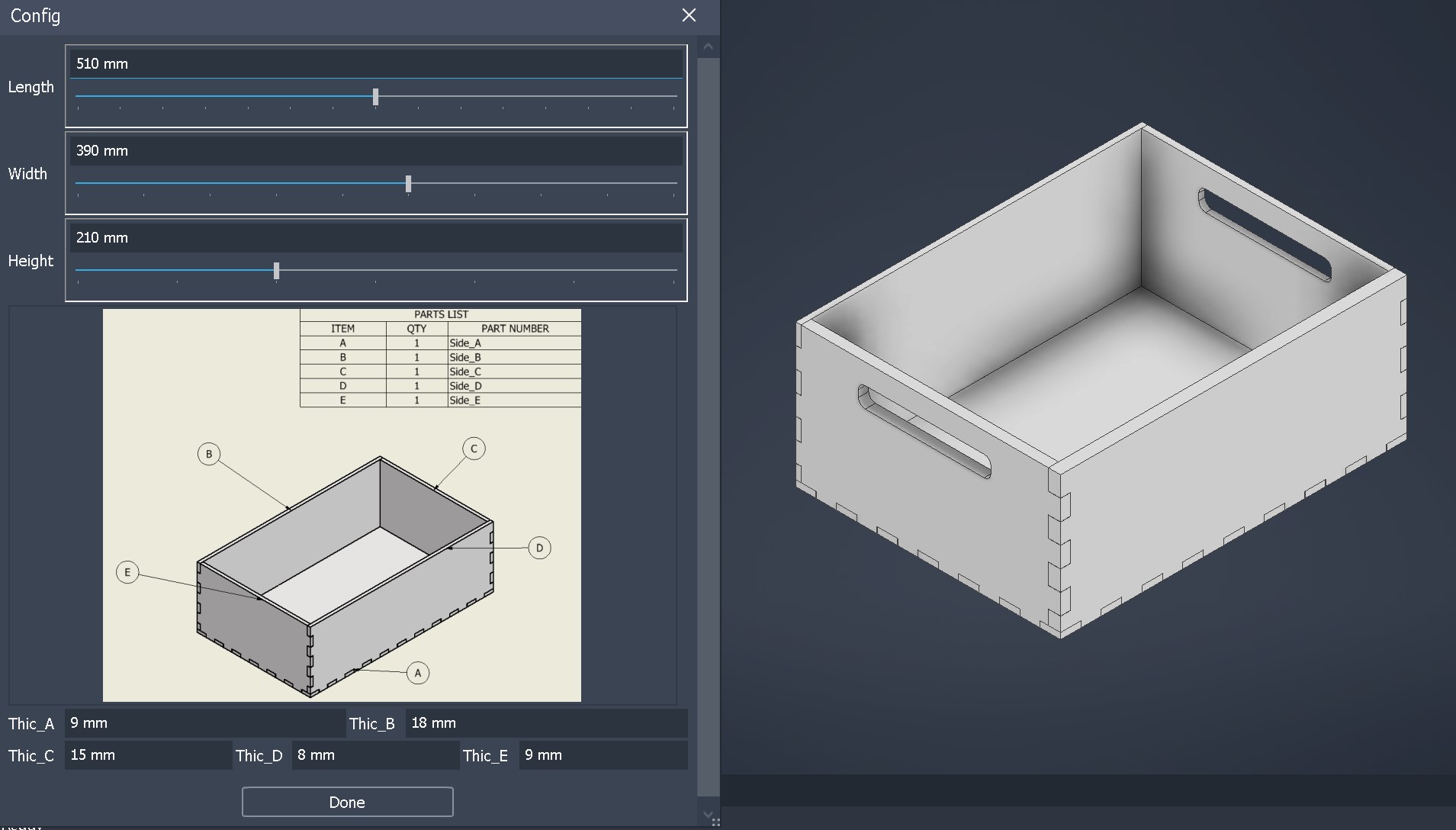
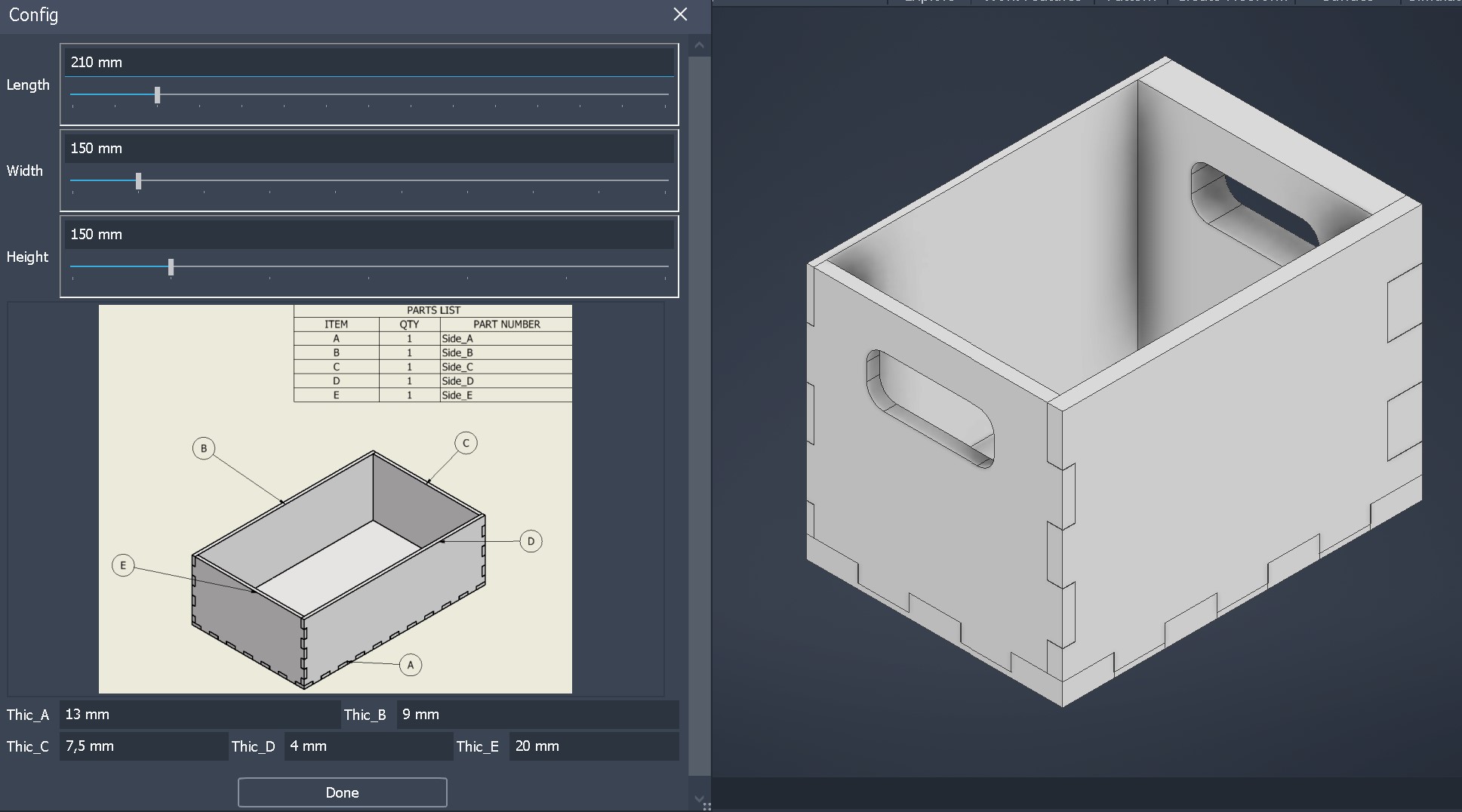
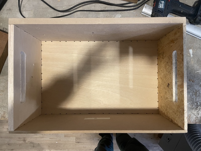
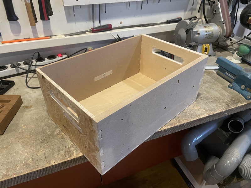
Explaining how I designed the part in Inventor using iLogic is beyond the scope of this article because it could be an entire course on its own. To confirm that the box is parametric, you can refer to Figures 1 & 2.
Figure 1Figure 2
Get your files ready
Step 1: Open VCarve Pro
Password PC FabLab: fablab
Open VCarve Pro 8.0 on the ShopBot PC
Step 2: Open file
In V carve it should be possible to open a lot of different files. In my case only .pdf worked. You can try what works for you.
Step 3: Specify material properties
measure and input the length and width of your material
meusure and input the thickness of the material
Set the z zero (origin point) on the bottom left of the material
Click OK
Step 3.5: Fix drawing
Because i could only open .pdf file i had to join all vectors. You do this by typing the letter j on your keyboard and than sellecting the complete drawing.
Step 4: Create fillets
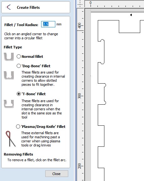
Under Edit Objects click on option Create Fillets and than in your drawing select the corners like in Figure 3.
You do this because it isn’t possible to mill 90 degree corners.
Figure 3
Step 5: Create drill holes
Under Create Vectors click on option Draw Circle
Set the diameter of the circle to the diameter of your tool
Place the circles in the corners of your material. Depending on the size of the material place circles between the corners. Do not place the circles in your drawing
Step 6: Toolpaths
In this step we create 2 toolpaths. one for the drill holes and one for the milling.
Drill Toolpath
Under 2D View Control click on option Switch to toolpaths tab
Under Toolpath Operations click on option Drilling Toolpath
Select all the circle that were just created
Set cutting depth to 2 mm
Make sure the correct tool is selected
Click on Calculate
Milling Toolpath
Under Toolpath Operations click on option Profile Toolpath
Select your drawing
The Cut Depth should be the same as the material thickness
Make sure the correct tool is selected
Machine Vetors... should be on the Outside
Check the box for Add tabs to toolpath and than click on Edit Tabs ...
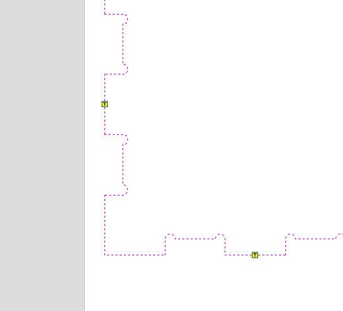
Place the tabs like in Figure 4, depening on the size of your drawing also place tabs in between
Click on Calculate
Figure 4
Preview Toolpaths
Under Toolpath Operations click on option Preview Toolpath
Click on Reset Preview
Click on Preview all Toolpaths
Now first the drill toolpath is played and than the profile toolpath. To close this window click on Close
Step 7: Save Toolpaths
Under Toolpath Operations click on option Save Toolpath
Select the Drill Toolpath and save it in your Folder (for example Box name) and give the file a clear name like Side_A_Drill
Do the same for the Profile Toolpath
Make sure you have 2 separete files
Working with the ShopBot
Step 1: Clear the machine
Remove everything on the table
Clear the space around the ShopBot
Step 2: Turn on the ShopBot
Turn on the computer
Turn on the Shopbot with the big red switch
Open the ShopBot software
Close the preview window
Type k for the keypad to move the toolhead around. It’s also possible to use the arrows and use the Page up and Down keys to move the toolhead up or down
Step 3: Calibrating the ShopBot
Make sure the correct tool is sellected, if not go to step 3.5
Click on Zero XY icon in the ShopBot software like in Figure 5
Figure 5
Zero Z-axes
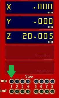
Place the metal plate underneath the milling bit. To make sure it works first thouch the milling bit and check if number 1 input lights up green Figure 6.
Click on Zero Z icon in the ShopBot software like in Figure 5
Place your material on the bed and set the milling bit to the origin point of your material
Zero X & Y in the ShopBot software by clicking on [Z]ero and in the dropdown menu click on zero [2] axes (X & Y)
Figure 6
Step 3.5: Changing milling bit
Lower the skirt of the dust extraction by unscrewing the butterfly screw till it can be lowered
Use the 2 wrenches (one of wich is connected to the key) to unscrew the nut
Change the bit for your tool
Remove collet from the nut
Match your tool diameter for the same collet diameter
Place collet back in the nut
Place the bit in the collet so that the bit matches the inner circle of the bit. Do this by looking from the top
Make sure the the milling depth is 2 mm less than the protrude milling bit
Use the 2 wrenches again to screw the nut back on
Move the skirt back up and thighten the butterfly screw
Step 4: Machining
Put on safety glasses and hearing protection
Turn on the dust extractor in the back of the room by pressing the green button
Turn on the Milling bit by turning the key on the side
When their is a problem press the spacebar on the keyboard
Drilling
Load the Drilling toolpath in the ShopBot software
Press Start and OK, the ShopBot will now start drilling
When the operation is finnished turn off the milling bit by turning the key on the side
Move the ShopBot with k on the keyboard
Screw the material to the bed on the places the ShopBot has drilled
Milling
Turn on the Milling bit by turning the key on the side
Load the Milling toolpath in the ShopBot software
Press Start and OK, the ShopBot will now start milling
When the operation is finnished turn off the milling bit by turning the key on the side
Unscrew your material
Step 5: Cleaning up
Vacuum the wood chips from the bed and incase ground
Turn off the ShopBot
Turn off the dust extractor With the red button
Turn off the PC
Step 6: Post-processing
Now it is time for post-processes all your parts and finnish the project.
This is my end result Figure 7 & 8.
Figure 7Figure 8]]>Sven Dekkersven-dekker@hva.nlIntroduction to Cricut Maker 32023-09-18T00:00:00+02:002023-09-18T00:00:00+02:00https://projectphase.github.io/documentation/inroduction-to-the-cricut-maker-3This article will take you step by step through the process of using the Cricut Maker 3 and share my experience.
The Cricut Maker 3 is a cutting machine designed for crafters and DIY enthusiasts. It allows you to cut various materials, including paper, vinyl, fabric, and more, to create a wide range of projects like custom cards, stickers, and textile designs.
I used it to cut my own stickers, and here is the step-by-step guide:
Step 1: Download Application
Download and install the Cricut Design Space from Cricut
I used Fusion 360 to design my sticker and exported the sketch as a vector file .svg
Step 3: Getting the machine ready
Place the Cricut on a table with enough room in front and behind for the material to go through the machine
Connect the Cricut to your PC
Place your chosen material on the cutting mat
Use the reference numbers in the Cricut Design Space to optimize your material placement
Step 4: Open Cricut Design Space
Create an account
Connect your machine
Start a new project with the green button in the top right corner
Upload your file
Add the file to the canvas
Position the file correctly using the reference numbers
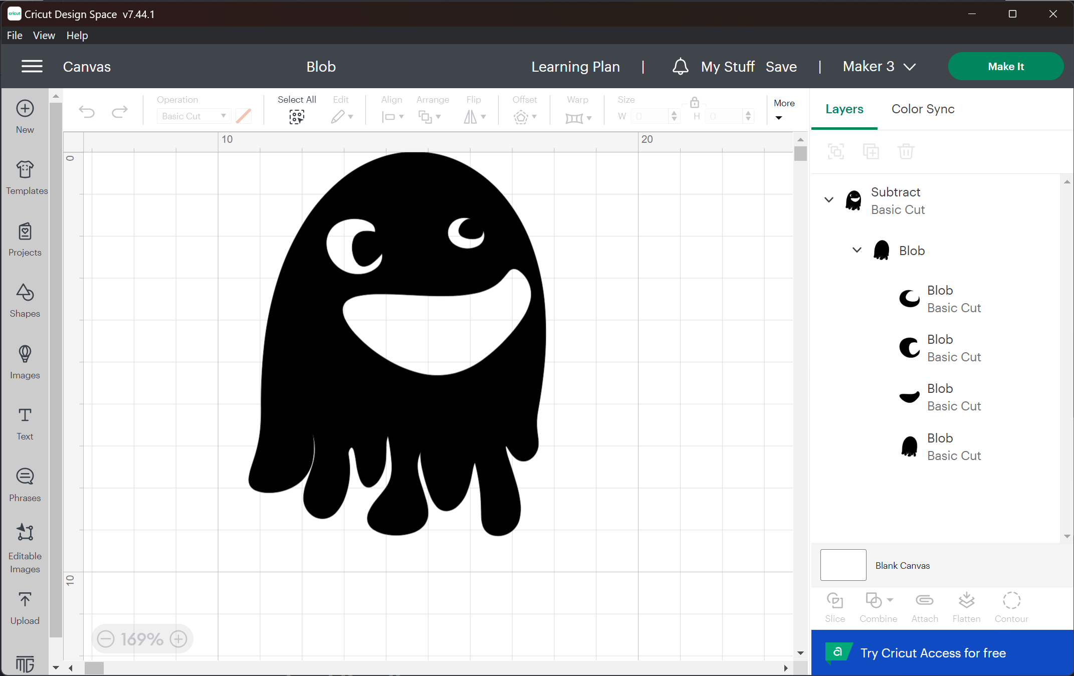
If your file contains multiple objects, you can select the object and choose one of these interactions: Weld, Unite, Subtract, Intersect or Exclude
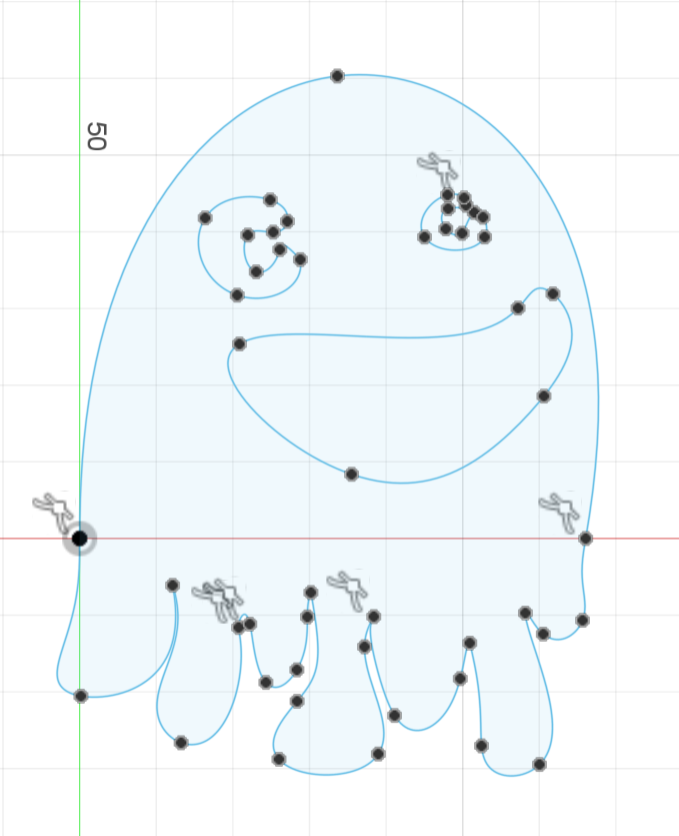
Blob in the Cricut Design Space
Step 5: Insert material into the Cricut
Press the arrows (< >) twice; this will take some time to home
Press the start button
Final Result
Blob in final form
To bring the cutting mat back out, press the arrows again
Now you are ready to peel off the sticker or cut it out to use later
]]>Sven Dekkersven-dekker@hva.nlIntroduction to a lasercutter2023-09-18T00:00:00+02:002023-09-18T00:00:00+02:00https://projectphase.github.io/documentation/introduction-to-the-lasercutterSven Dekkersven-dekker@hva.nlSub-Product 1: Research and Requirements Specification2023-09-15T00:00:00+02:002023-09-18T00:00:00+02:00https://projectphase.github.io/multi-material%203d%20printing/Sub-Product-11. Research
In the research, the research questions (sub-questions) are answered one by one with justification. For this purpose, reference will be made to the used sources using the APA method.
1.1 What specific multi-material 3D printing products exist?
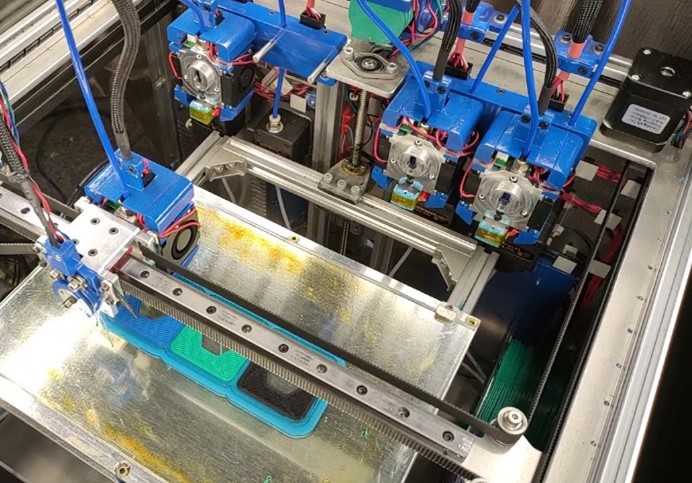
In Chapter 2 of the “Plan of Approach,” under the heading “Problem Statement,” six different methods for multi-material 3D printing are discussed: MMU, Filament splicing, Dual extruder printhead, IDEX, Toolchanger, and CNC nozzle changing. Before specific products are examined, it is important to determine which of these methods are not suitable for the assignment, within the defined scope and in line with the objectives. Therefore, each method will now be briefly discussed.
1.1.1 Further investigate
Figure 1
1.1.1.1 MMU
It’s interesting that multiple materials can be printed with a single extruder. However, it’s unfortunate that material needs to be purged from the hotend. Could this be resolved? Is this an interesting solution?
Further investigate = ✔
Figure 2
1.1.1.2 Filament splicing
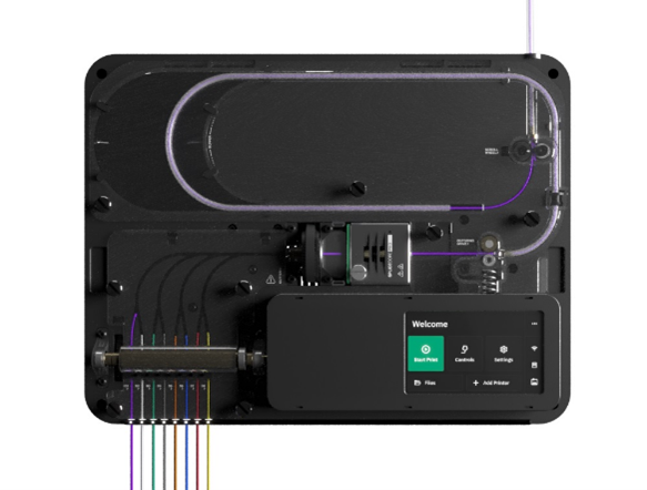
The market for existing products is limited. Currently, there is only one known product that utilizes this technology, namely the Palette 3 by Mosaic, priced at $599 Figure 2. When we search for Review Palette 3 on “Duck Duck Go”, the first link leads to a Reddit discussion. In the discussion, opinions are generally negative, and furthermore, this technology has not seen any innovative or developmental advancements for quite some time.
Further investigate = ❌
1.1.1.3 Dual extruder printhead
Calibrating a “Dual nozzle hotend” can be challenging because you need to precisely adjust two points on the print bed to the same level. If these points are not equal, it can be difficult to properly align the two print heads since there may be limited or no adjustment options. This is also highlighted in an article on xyzdims.com.
Further investigate = ❌
The initial impression of the “Dual Switching Hotend” appears to be a reasonable solution for printing with two materials. However, adding more print heads does not seem like a suitable idea due to potential issues related to weight, precision, and complexity. This can be gleaned from the Multiple Switching Extrusions project
Further investigate = ❌
1.1.1.4 IDEX
For multi-material 3D printing with two materials, IDEX technology appears to be one of the most suitable methods. This approach has extensive online documentation. However, innovating this technique can be challenging, and furthermore, it is limited to the use of only two materials.
Further investigate = ❌
1.1.1.5 Toolchanger
The toolchange method is most commonly used in the professional industry. This is because it offers many possibilities in terms of materials, nozzle diameters, and potentially other tools. Cost considerations are less significant for large companies. In cases where costs can be kept limited, this method is also interesting.
Further investigate = ✔
1.1.1.6 CNC nozzle changing
The Swapper3D by BigBrain3D is currently the only one on the market that performs a nozzle change similar to a CNC tool changer. This concept provides the opportunity to create various variations, and there is still ample room for innovation in this field.
Further investigate = ✔
1.1.2 MMU
In this chapter, various MMUs (Multi-Material Units) are examined and evaluated.
Figure 3
1.1.2.1 Prusa MMU (spcific MMU2)
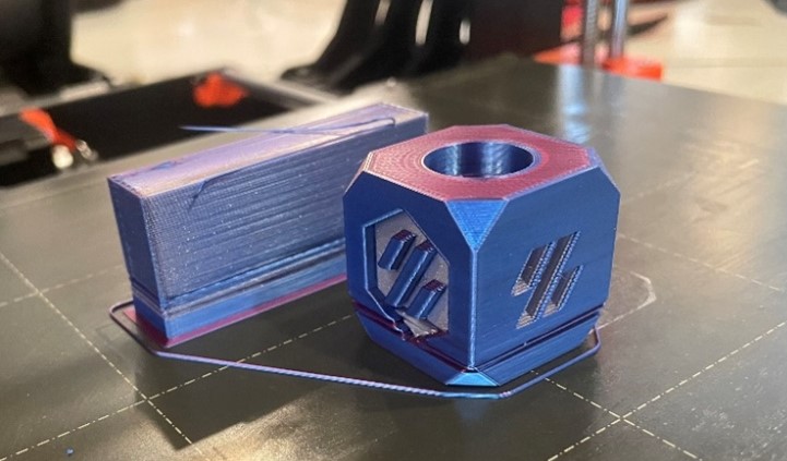
At Waag FabLab, they have a Prusa MK3 with an MMU2. To gain experience for this project, a calibration cube was printed with two colors to keep the complexity low. It took two days to achieve a semi-successful print Figure 3. The filament switch did not go well on various layers, resulting in the printer not producing anything. To obtain this result, more than 6 interventions were required, mainly at the beginning. This print with one color takes 1 hour and 15 minutes, and with two colors, it takes 4 hours and 34 minutes, which is also a significant drawback.
After having 5 unsuccessful prints and 1 semi-successful print, it can be concluded that this MMU is not reliable, and it should not serve as an example.
Meanwhile, Prusa has released an MMU3 priced at €329 with better reviews. The most significant drawback mentioned in the review is “The problems start when trying to use mixed materials or PETG” Reddit - Dive into anything. Printing with various materials is precisely the goal.
Figure 4
1.1.2.2 Enraged Rabit Carrot Feeder (ERCF)
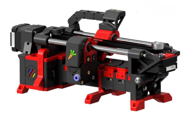
This is an open-source MMU, and all the documentation is available on GitHub. Within this documentation, you can also find a link to the BOM (Bill of Materials) with various links to websites where the components can be purchased. It is clearly indicated that these are affiliated links. Kits are also available from other suppliers for around €150.
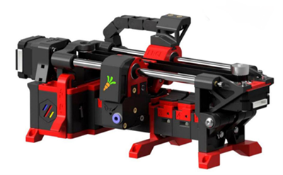
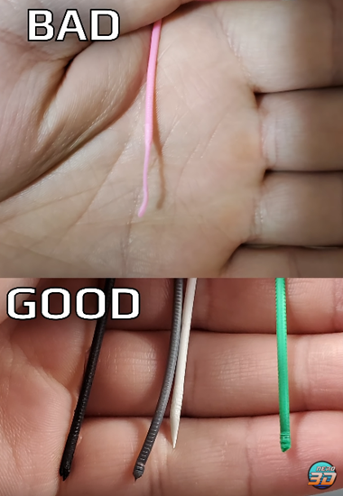
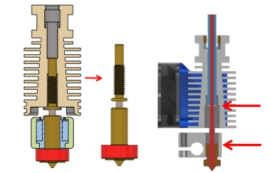
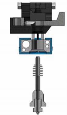
The video review by NERO 3D discusses both the strengths and weaknesses, as well as some issues and successes. One of the biggest problems the reviewer encountered was the improperly shaped filament end during retraction Figure 4. Later, it was found that this was due to an unsuitable combination of the hotend and nozzle. The old hotend consists of multiple parts, which can result in plastic getting stuck in various places Figure 6. However, the new hotend, the RapidChange Revo, has a nozzle with an integrated heatbreak. This has the advantage of preventing any snagging due to the smooth interior Figure 5. Additionally, the reviewer noted that even if you’re not printing with all 6 materials, you always have 6 materials available without the need to change filament rolls each time.
Figure 5, Figure 6Figure 7
1.1.2.3 3DChameleon
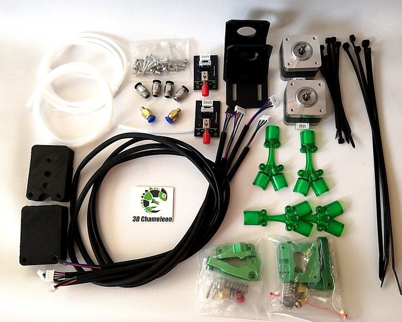
The 3DChameleon mk3 costs $179 with shipping costs of €220 and can switch between four colors. Their website explains how this system works. They describe it as follows:
The 3D Chameleon operates by utilizing your 3D printer’s existing mechanical hardware to automatically remove and reload filaments when a color (or material) change is needed. By leveraging your existing electronics, we can use standard GCode commands to tell the 3D Chameleon which color to select.
Home of the 3DCHameleon
To simplify this explanation, the 3DChameleon uses its own microcontroller and a button. During a filament change, the G-code includes instructions to press the button a certain number of times for the desired color, allowing the microcontroller to know which color to load. There is no direct integration between the printer and the 3DChameleon. This makes it a suitable product for more affordable printers like the Ender 3 V2 and other similar models.
Figure 8
1.1.2.4 ROME
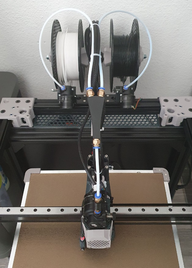
The explanation of ROME on HelgeKeck’s GitHub repository ROME is much faster than a regular MMU or ERCF setup. The entire process of loading and unloading filament is several times faster, not only because ROME simply needs to park the filament behind the Y-split. In its own mode, ROME handles the filament loading and unloading, skipping the phase controlled by the slicer. This process is highly optimized for a specific Hotend/Filament combination.
A significant time-saving, as HelgeKeck explained, is that the filament only needs to be parked behind the Y-split. For each filament change, this may be only a few seconds, but with quickly accumulating more than hundreds of filament changes, this adds up. This also applies to the 3DChameleon.
Figure 9
1.1.2.5 Bambu Lab
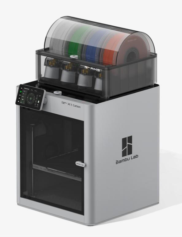
Bambu Lab is a prominent player in the 3D printing industry, particularly in the field of multi-material printing. Their printers, the P1P (€1015.80 incl. AMS) and the X1-Carbon (€1524.19 incl. AMS), have proven to be significant successes, especially when used with their Automatic Material System (AMS) priced at €365.03. However, it’s important to note that the AMS is specifically designed for use with their own printers and is not compatible with other brands.
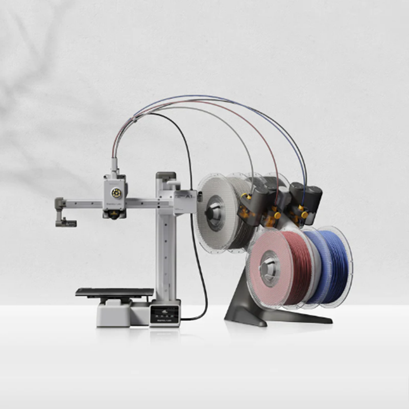
Recently, as of the day of writing, Bambu Lab has launched a new system, the A1-mini (€497.21 incl. AMS Lite), in conjunction with the AMS Lite.
Figure 10
The AMS Lite is an evolution of the AMS system, with some notable improvements. Filament spools are now placed in the center instead of on the outside, which is convenient for using cardboard spools. Additionally, the splitter, where the filament is retracted to, is now directly above the extruder rather than in a separate box above, which was previously seen as a positive change. Moreover, the amount of plastic that needs to be purged with this system has been reduced.
Although Bambu Lab’s products are not open source, they currently offer a wide range of individual spare parts on their website. This may provide opportunities for the development of an open-source multi-material unit, which is included in the research question “Which purchased components offer possibilities within the budget.” It is difficult to predict how long they will continue to offer spare parts.
1.1.3 Toolchanger
In this chapter, various tool changers are investigated and evaluated.
Figure 11
1.1.3.1 E3D ToolChanger
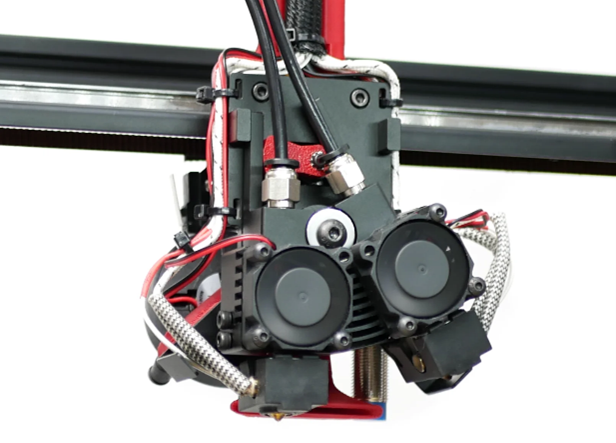
E3D, which stands for “Engineering 3D Printing Solutions,” was one of the first leading manufacturers to introduce the ToolChanger system in 2019, marking a significant breakthrough. Many open-source toolchangers are still based on their technology.
The toolchanger mechanism has three contact points that are reasonably spaced apart on the exterior for stability. To securely hold the tool, a key is used that rotates a quarter turn. Figure 11 shows the printhead, and Figure 12 displays the tools.
Figure 12
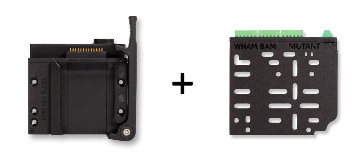
1.1.3.2 Wham Bam: The MUTANT V2
The MUTANT V2 is a universal tool-changing system that offers the possibility to make your FDM printer more versatile. It allows for easy swapping of the hotend with tools such as laser cutters, pen plotters, vinyl cutters, and more. However, this system is not intended for changing tools within a 3D printing process.
The elegance of this design lies in the two plates easily sliding together using a dovetail connection and securely locking in place with a lever. Electrical contact is managed through a series of pogo pins, also known as spring contact pins or compression spring pins. This is ideal for tool changers.
Figure 13Figure 14
1.1.3.3 XChange
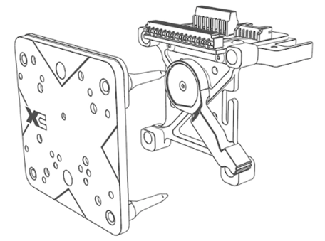
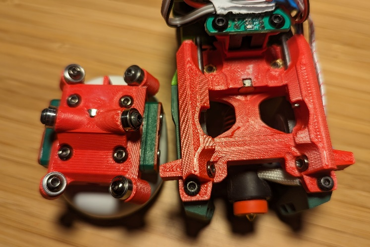
XChange by PrinterMods is a quick-change tool head for any 3D printer. This product is not yet available but is live on Kickstarter, where they are still seeking backers.
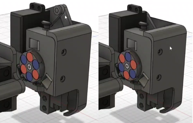
This product bears a resemblance to the MUTANT V2. In both products, it’s not possible to change tools during the print, but XChange approaches the coupling differently, offering potential possibilities. XChange utilizes magnets and pins, allowing the coupling to move only forward and backward, unlike the MUTANT V2, which also involves vertical movement.
The detachment is achieved by using the polarity of the magnets. Moving the lever upward causes the magnets to rotate so that they repel each other. This can be clearly seen in Figure 15, which is a different design but follows the same principle.
Figure 15Figure 16
1.1.3.4 Tapchanger
Tapchanger is an open-source project by Viesturz GitHub repository Tapchanger.
The concept behind his design is that you don’t need servo motors or other moving parts to couple and uncouple it. A sensor is used to verify the successful coupling and uncoupling.
Viesturz has shared the CAD files along with a Bill of Materials (BOM) and other documentation in a GitHub repository. He is also actively participating in a Discord channel called “Voron Toolchangers Discord.”
1.1.4 CNC nozzle changing
In Chapter 2 of the “Plan of Approach,” in the “Problem Statement” section, we have already extensively discussed The Swapper3D. Currently, there are no other products on the market that apply the same method. The concept of combining each material or color with its own nozzle is exceptionally inspiring. What’s interesting is that in recent years, and even months, new products have emerged on the market that enable innovation within this concept. This will be further explored in research question 3.
1.2 What tool change methods exist in other production machines?
Figure 17
3D printers are not the first machines where tool changes are desired during production. Inspiration can perhaps be drawn from existing methods.
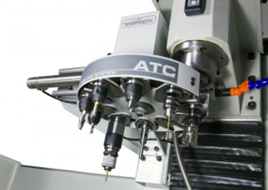
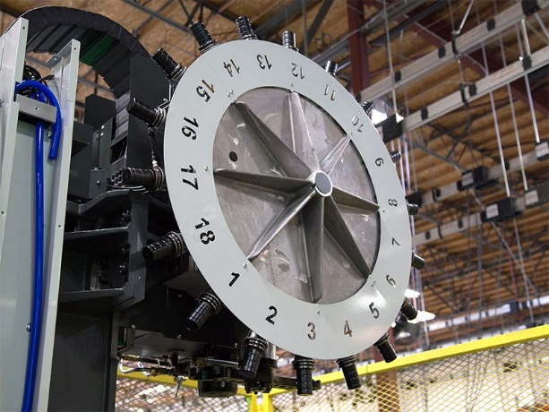
1.2.1 Carousel Automatic Tool Changer
Also known as a Carousel Automatic Tool Changer, it is an essential component commonly found in CNC machines. Its primary purpose is to automate the process of changing tools during machining operations, thereby improving efficiency and reducing downtime.
Disadvantages:
Figure 18
High complexity with more moving parts
The parts are not designed for 3D printers
Existing printers like the Ratrig Vcore-3.1 and Voron printers require significant modifications to create space for a carousel. A Side Mount Carousel Automatic Tool Changer Figure 18 could be of assistance in this regard, as seen with the Swapper3D Figure 20, but the complexity remains.
1.2.2 Linear automatic tool changer
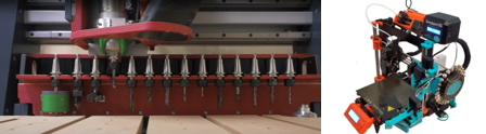
Also known as a Linear Automatic Tool Changer, it is a device commonly used in machining centers and CNC machines to automate the process of changing cutting tools during various machining operations. In contrast to the Carousel automatic tool changer, which uses a rotating tool storage carousel, a linear automatic tool changer employs a linear motion mechanism to achieve tool changes.
This technique is also evident in current toolchanger 3D printers.
Figure 19, Figuur 20
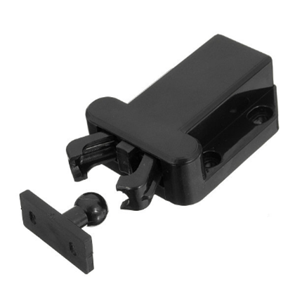
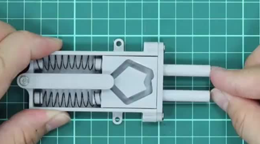
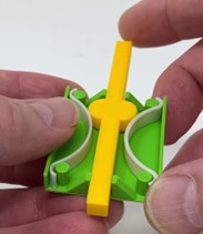
1.2.3 Push to release mechanism
In the event that the tool change method is to be used, there are various options to mechanically secure the tool without the need for motors. This helps keep costs low. The complexity of the suspension is higher, but you do not need to program and connect one less motor.
The best examples are drawer locks. There are three images of three different technical mechanisms. Figuur 21, 22, 23
Figure 21, Figure 22, Figure 23
1.3 What purchased components offer possibilities within the budget?
1.3.1 RapidChange Revo
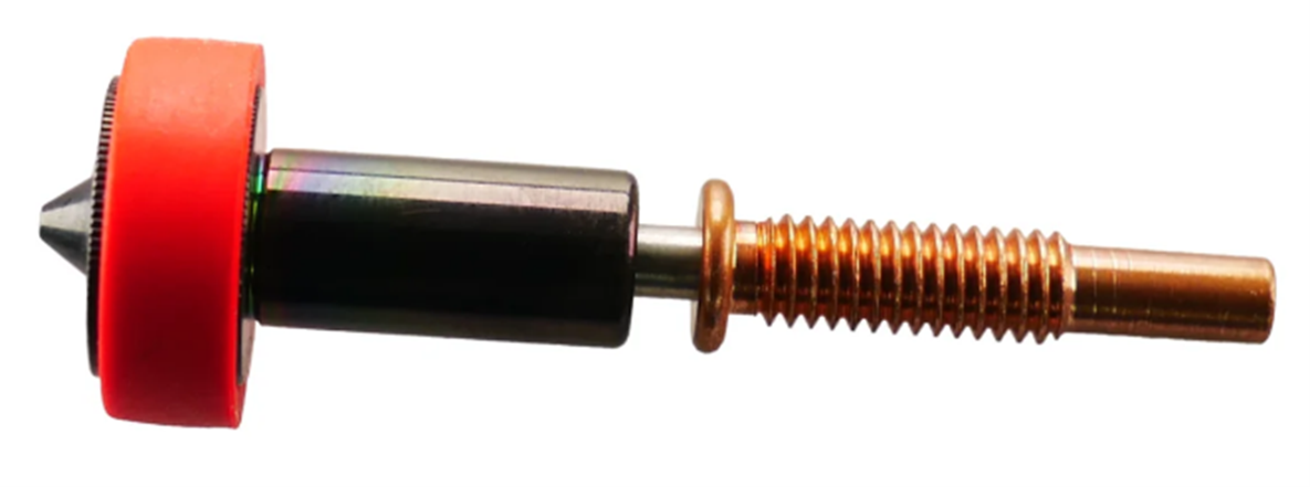
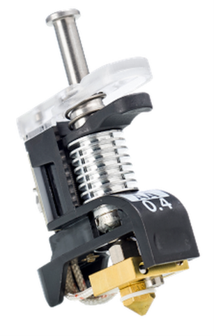
Unlike other nozzles, the Revo hotend can be easily swapped by the user for €26.99. This is because the heatbreak and the nozzle form a single object. Furthermore, the hotend can be gripped by the silicone sock and hand-tightened.
To tighten the Revo, it takes about 15 revolutions. This would be automated using a stepper motor and the same software technology as sensorless homing. Sensorless homing utilizes the motor and the load it moves to determine when the component has reached its end position.
Figure 24Figure 25
1.3.2 Bambu Lab hotend
Bambu Lab offers a printer, the A1 mini, for which they provide a wide range of spare parts and accessories. They also offer their hotend heating construction and hotends with nozzles Figure 25. “The Hotend heating construction is specially designed to support the fast-changeable hotend design. A quick clamping mechanism is used to secure the heating block and the heating base, enabling easy separation of the thermal and electronic components of the hotend” Bambu Lab
So, a one-time purchase of the hotend heating construction is needed, priced at €21.34, and for each additional hotend with a nozzle, the cost is €13.21. These products allow for the easy replacement of just the hotend with the nozzle. With this concept, all the cables are kept on the printhead, eliminating the need for an extra extruder, hotend fan, and part cooling fan. This can significantly reduce costs and complexity.
Figure 26
1.3.3 QuickSwap - Hotend and Insert
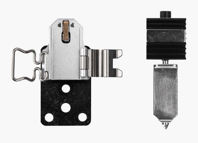
BigBrain3D also offers their QuickSwap Hotend Figure 26 separately for $99. They sell the inserts separately for $24.99, but you still need to add your own nozzle. These products also provide possibilities. However, they are currently out of stock. BigBrain3D is not a well-known name in the 3D printing world, which also doesn’t provide certainty for the future.
Figure 27
1.3.4 Ultimaker print core
UltiMaker offers quick-change print cores for their S-series at a price of $114.95. However, the cost of a hotend with a nozzle is too high to integrate into an open-source multi-material 3D printer. Nevertheless, the attachment mechanism is very robust, as can be seen in the GIF on the MatterHackers website. Inspiration can be drawn from this.
1.4 What possibilities exist between the slicer and G-code?
Klipper has a fairly basic interrogation for multiple extruders/printheads. To assign individual variables to each extruder/printhead, the user must create macros themselves.
1.4.1 Tools for klipper (KTCC-Klipper Tool Changer Code)
TypQxQ has created something here to provide a basic configuration. This is called “Tools for Klipper” (KTCC - Klipper Tool Changer Code).
These are Python modules, macros, and example configurations for the Klipper 3D printer firmware to operate as a tool changer.
In its simplest form, you need to specify the extruder, fan, and offset for each printhead. Then, add your macros for picking up, dropping off, locking, and unlocking tools.
The multi-extruder setup ROME by HelgeKeck, as discussed in 1.1.2 MMU, has its own Klipper plugin created. This only needs to be installed and requires very little user input. GitHub repository ROME
1.4.3 Happy Hare
Happy Hare is a Universal MMU driver for Klipper. It simplifies the configuration and calibration of MMUs. Depending on the specific brand of your MMU, the calibration may vary slightly, although the steps are essentially the same for all brands. GitHub repository Happy Hare
1.5 What methods can switch materials within 30 seconds?
To gain a better understanding of the discussed products, the key information has been summarized in a table. The time estimates are based on YouTube videos of the products, and due to variations in settings, the times are approximate. In the “Wipe tower” column, it is indicated whether the wipe tower consists of more than just a single line of plastic. In cases where “no” is listed, there may still be a wipe tower with a single line to ensure that the plastic flows normally, as oozing can cause plastic to flow out of the nozzle when it’s not in use.
Time
Wipe Tower
Costs
Prusa MMU
>60 sec
Yes
€329,-
ERCF
>60 sec
Yes
€150,-
3DChameleon
>60 sec
Yes
€220,-
A1 mini
>90 sec
Yes
€497,-
*
E3D Toolchanger
>30 sec
No
€2956,-
**
Tapchanger
>30 sec
No
€500,-
***
Swapper3D
>30 sec
No
€400,-
* Currently, can only be purchased in combination with the printer
** Printer in combination with 4x direct drive extruder tool changers
***Adding 4 tool changers
2 Program of requirements
The program of requirements is an important tool to kickstart the creative thinking process and ultimately define a final design.
2.1 Requirements
No.
Requirements
Unit
Source
Date
Verification
1
3D printing of 2 or more materials
Numbers
Sven Dekker
27-09-2023
Performance after realization
2
Applicable to 2 or more 3D printers that may vary in size
-
Sven Dekker
27-09-2023
Assembly after realization
3
Cost is less than €350
Euro
Sven Dekker, based on similar products
27-09-2023
Sum of costs of the final product only
4
Changing material takes less than 30 seconds
Seconds
Sven Dekker
27-09-2023
Timing after realization
5
Feasible for anyone with a 3D printer
-
Sven Dekker
27-09-2023
Verification after realization
6
Open-source sharing of the project
-
FabLab Waag
27-09-2023
Downloadable via Github
7
Reliability so no user interaction is required during 3D printing
-
Sven Dekker
27-09-2023
Checking interactions during print
8
3D printer automatically calibrates when calibration is needed after initial setup
-
Sven Dekker
27-09-2023
No manual calibration
2.2 Success criteria
Requirement No.
Requirement
1
The Multi-material addition can 3D print with as many materials as possible
2
The Multi-material addition can be mounted on as many printers as possible
5
The Multi-material addition consists of as many 3D print components as possible
7
The Multi-material addition must be as reliable as possible
8
The Multi-material addition requires as few user interactions as possible after installation on the printer,
]]>Sven Dekkersven-dekker@hva.nlPlan of approach2023-09-15T00:00:00+02:002023-09-18T00:00:00+02:00https://projectphase.github.io/multi-material%203d%20printing/plan-of-approach1. Introduction
In this chapter, the research topic is introduced along with the associated assignment. This aligns well with the FabLab, as explained in the organization description section.
1.1 Research topic
3D printers are highly accessible nowadays and have undergone significant development over the past decades. You don’t need to spend more than 200 euros to purchase a decent printer. This is fantastic for anyone who owns a printer because it encourages the sharing of more 3D files and the development of new printing techniques. One of the upcoming developments in this sector is multi-material printing. This offers advantages such as creating 3D prints that combine different materials, printing with various nozzle diameters (making infill, for example, print faster), water-soluble support printing, and multi-color prints.
For these reasons, there are already several solutions on the market. Each of these solutions has its pros and cons, but in many products, the disadvantages outweigh the advantages. Therefore, the plan is to design a product in which the benefits outweigh the drawbacks.
1.2 Assignment
“Develop a system that enables printing with multiple materials on existing printers.”
The assignment comes with the following conditions:
Printing with 2 or more materials
Applicable to 2 or more printers, which may vary in size
Costs are less than €350
Changing materials takes less than 30 seconds
Feasible for anyone with a 3D printer
1.3 Organization description
On the website of FabLab BeNaLux, they describe the philosophy behind the organization as follows:
A FabLab is a public digital workshop where people are invited to create things themselves using various techniques, and where the open sharing of designs and ideas is encouraged. In other words, a FabLab is a workshop that provides easy access to a range of computer-controlled prototyping machines, allowing users to transform their ideas into tangible products.
A FabLab typically includes a laser cutter, a CNC milling machine, a 3D printer, a vinyl cutter, and an electronics corner.
An important characteristic of Fablabs is that they share their knowledge with other Fablabs. They often serve as breeding grounds for innovations.” (FabLab BeNeLux, 2017)
There is currently no perfect solution for multi-material 3D printing; every product on the market has its drawbacks. In this chapter, the disadvantages/problem statements are described, from which the main and sub-questions are derived.
2.1 Problem Statement
To clarify the problem statement, an explanation of what is already available on the market will be provided. These products address multi-material printing in various ways. The advantages are omitted because every product ultimately boils down to the ability to print with multiple materials, placing more emphasis on the disadvantages.
2.1.1 MMU (multi-material unit)
Figure 1
It is an addition to single-extruder printers to enable printing with multiple materials. The unit facilitates filament exchange, allowing filaments to be retracted from the extruder and replaced with another during printing.
Disadvantages:
Time and material wastage: Each material change takes more than 30 seconds, and material purging is required. This means that dozens of millimeters of material are pushed through the nozzle to clear the color and material. In slicers, they try to cleverly address this by using the purge tower as part of the actual print, but this is not ideal.
Complexity: Building an MMU like the open-source ERCF (Enraged Rabbit Carrot Feeder) is highly complex, with the assembly manual spanning over 130 pages.
2.1.2 Filament splicing
Figure 2
Filament splicing is a technique used in 3D printing to join two segments of filament together, creating an uninterrupted filament strand. This is employed to print with multiple filament colors or materials. The slicer indicates the right moment to combine the filaments to achieve the desired color effects or material transitions in your 3D prints.
Disadvantages:
Calibration: You need to accurately set the length of the splicer to the printhead to ensure that the filament change occurs at the right moment.
Purge tower: Filament splicing also requires the presence of a purge tower.
2.1.3 Dual hotend
Dual hotends are available in various configurations. Some models feature two print heads placed side by side Figure 4, while others use a system that switches between one hotend and the other Figure 3.
Disadvantages of the “Dual Switching Hotend” Figure 3:
Figure 3
Bowden extruder: A Bowden extruder is a component of a 3D printer where the extruder (the motor that feeds the filament) is located remotely from the print head and transports the filament to the print head through a tube. Bowden extruders are less suitable for flexible filaments, retract settings are critical, and long-distance accuracy is challenging due to filament pressure affecting tube bending.
Disadvantages of the “Dual Nozzle Hotend” Figure 4:
Figure 4
Oozing: Oozing is the undesired leakage of molten filament from the print head when, in this case, the other print head is active. This leakage results in droplets or thin filament strands being deposited in places where they shouldn’t be or even pushing the print object off the bed.
2.1.4 IDEX (Independent Dual Extruder) 3D printing
Figure 5
IDEX is a type of 3D printer that features two independent print heads, and these print heads can move independently along the x-axis. One unique advantage that no other 3D printer offers is the ability to print two objects simultaneously.
Disadvantages:
Reduces print surface area: Adding a print head to an existing 3D printer reduces the available print surface area on the print bed.
2.1.5 Toolchanger
Figure 6
A toolchanger is a component or system used in advanced 3D printers to automatically switch between different tools, such as print heads, laser engravers, cutting plotters, and more, during the printing process. The primary purpose of a toolchanger is to enhance the versatility of a 3D printer by offering various functions without requiring the user to manually change tools.
Disadvantages:
Cost: For each additional material you want to use in a print, you need an extra print head. The components you need to purchase additionally include an extruder, hotend, extruder cooling fan, part cooling fan, and print head. These costs can add up quickly.
Complexity: A toolchanger requires complex software and firmware configurations to coordinate the correct tool choices and movements. This involves calibrating the pickup and drop-off locations of the print head, which can be a significant learning curve.
Reliability: Maintaining reliability becomes increasingly challenging as the number of moving parts increases. Issues related to alignment, component wear, and calibration can arise, resulting in reduced reliability and unexpected downtime.
2.1.6 Cnc nozzle changing
Figure 7
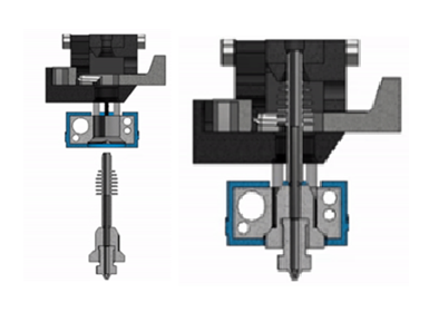
The Swapper3D by BigBrain3D is the only one on the market that performs a nozzle change similar to a CNC tool changer. They achieve this with many moving parts and their own extruder and nozzles. The nozzle enters from beneath the hotend and is secured with a pin at the top Figure 7. (The Swapper3DTM: No more purge blocks! – BigBrain3D, n.d.)
Disadvantages:
Figure 8
Complexity: This design involves even more moving parts than what was mentioned with tool changing, making it quite complex.
Proprietary: The hotend and nozzle are proprietary to BigBrain3D and not available as open source, and the cost of these products is considerably high.
2.2 Delimitation/Objective
The project is to create an open-source product that potentially innovates on existing products to enable multi-material printing on existing 3D printers. In this context, the existing platform is not or minimally modified, and the focus is on providing an addition.
For which 3D printers:
The fundamental open-source 3D print platforms for this purpose are the Ratrig V-core 3.1 Figure 9 and the open-source 3D print platforms Voron Trident or Voron 2 Figure 10.
Figure 9, Figure 10
Timeline:
Within 6 months.
Product delivery:
A physical product with publicly available documentation. This includes electronic connections and software and firmware configurations.
2.3 Main quesetion
What is the best add-on for existing 3D printers that enables multi-material printing?
2.4 Sub-question
To answer the main question, the following sub-questions have been formulated:
What specific multi-material 3D printing products exist?
Under the problem statement, all overarching methods have been discussed. Within these overarching methods, there are also specific products that can be examined.
What tool-changing methods exist in other production machines?
3D printers are not the first machines where tool changes are needed during production. Perhaps there are lessons to be learned from other manufacturing machines.
Which purchaseable components offer possibilities within the budget?
There are many different types of extruders, hotends, and nozzles on the market today. Development in the field of 3D printers is very active. Are there purchasable components that can create new possibilities, improve options, or make methods more cost-effective?
What possibilities exist between the slicer and G-code?
The slicer generates the G-code. What are the possibilities for including additional information in the G-code, and how can it be ensured that the 3D printer’s computer can read and execute this information?
What methods can change materials within 30 seconds?
Create a table outlining which products can switch materials within 30 seconds and without wasting plastic.
To obtain answers to these sub-questions, research will be conducted, as described in the product delivery section. It is also possible that new and additional questions may arise during the design process, and these will be addressed in part 1 of the project.
3. Activities and Deliverables
In this chapter, we will describe the activities and deliverables that will be provided to answer the main research question.
3.1 Sub-product 1: Research and Project Requirements
In this sub-product, the following activities and deliverables will be included:
3.1.1 Activities
In sub-product 1, an analysis will be conducted to address the research questions outlined in Chapter 2, with a general approach already indicated.
The activities to be performed include:
Using search engines and YouTube videos to research the topics mentioned in the research questions in Chapter 2.
Consulting various Discord channels.
Documenting the project requirements based on the research questions and the established constraints.
3.1.2 Deliverables
The deliverable for the research phase is a research report in which the research questions will be systematically answered one by one with substantiated explanations. Proper referencing of sources will be done using the APA method.
3.2 Sub-product 2: Solutions for Sub-Functions
In this sub-product, the following activities and deliverables will be included:
3.2.1 Activities
A functional analysis will be conducted, followed by a brainstorming session. From this brainstorming session, potential solutions for the defined functions will emerge. These solutions will be represented as small sketches in a morphological overview. For each of the functions, at least 3 solutions will be sketched.
Functional analysis
Brainstorming session
Morphological overview
Any necessary experiments
Any necessary calculations
3.2.2 Deliverables
The deliverable is a report that presents the activities conducted. The morphological overview will be presented in A3 format, and the ideas will be substantiated.
3.3 Sub-product 3: Concept Designs
In this sub-product, the following activities and deliverables will be included:
3.3.1 Activities
Based on the morphological overview, concept designs will be generated. Lines will be drawn for each concept, connecting potentially complementary solutions. The number of concepts will depend on the possibilities presented in the morphological overview. The concepts will be presented as drawings and descriptions of the entire product, including the functionality, form, and operational principles of the product.
3.3.2 Deliverables
The concepts will be delivered as follows:
For each concept, a 3D drawing with multiple 2D views.
An explanation of the operational principle.
Identification of the strengths and weaknesses of each concept.
Key dimensions will be specified.
Mechanical functions will be clearly indicated.
These concept designs will serve as the foundation for further development and evaluation, providing a range of potential directions to explore.
3.4 Sub-product 4: Detailing of the Chosen Concept
In this sub-product, the following activities and deliverables will be included:
3.4.1 Activities
A selection matrix will be created, consisting of success criteria to which weighting factors are assigned, and these factors will be substantiated. This matrix will be used to evaluate the concepts and provide them with a meaningful ranking.
Following that, the chosen concept design will be detailed extensively. All aspects of the final design will be specified, including assembly drawings, exploded views, and component drawings in Inventor or Fusion 360. Additionally, a numbered parts list with references to the drawings will be provided. For purchased components, all specifications will be documented to facilitate procurement.
This is also the stage to consider the control system of the concept. It involves referencing how others manage the control of similar products and exploring programming languages that might be used for controlling the concept effectively.
3.4.2 Deliverables
The deliverable for sub-product 4 is a report that consolidates the following components:
Drawings: assembly drawings, exploded views, and individual part drawings.
Bill of Materials (BOM).
All specifications for purchased components.
Material selection for fabricated parts.
xDraft code for controlling the concept.
These detailed documents will provide a comprehensive understanding of the chosen concept design and enable its practical realization.
3.5 Sub-product 5: Construction and Testing of the Prototype and Evaluation
In this sub-product, the following activities and deliverables will be included:
3.5.1 Activities
Build a prototype based on the detailed design, with the goal of demonstrating the functions outlined in the detailed design.
Connect the prototype to the printer to enable control of the prototype.
Then, the challenge is to program the slicer and 3D printer to make the prototype perform its intended functions. Depending on this process, it may be necessary to modify the concept to make the functions achievable. To draw meaningful conclusions from the tests, test procedures will be defined in advance, covering the research question, hypothesis, test setup, test procedure, results, and conclusion.
Once the test procedures are completed, an evaluation will take place. This evaluation will assess the extent to which the final result meets the requirements and success criteria from the Project Requirements and identify areas for further innovation. It will also revisit the research questions, considering whether new questions have emerged due to evolving insights or whether existing questions need further investigation. Based on the evaluation, the concept will be improved or potentially canceled to explore alternative directions.
3.5.2 Deliverables
The deliverable for sub-product 5 is a report that consolidates the following components:
Physical prototype.
Report with photos documenting the construction process of the prototype.
Test procedures and test results.
Demonstrative videos of the performed tests.
Documentation of the evaluation and its outcomes.
Open-source contributions to the Project.
These deliverables will showcase the real-world implementation and testing of the chosen concept, providing insights into its feasibility and performance.
]]>Sven Dekkersven-dekker@hva.nlSetting up a static website2023-09-12T00:00:00+02:002023-09-13T00:00:00+02:00https://projectphase.github.io/documentation/setting-up-the-static-websiteThis article will take you step by step through the process of building your own static website.
To build our website we use Jekyll. Jekyll is a popular static site generator used for building and managing websites and blogs. It’s an open-source tool written in Ruby and often used by developers, bloggers, and content creators. Jekyll takes plain text files, often written in Markdown or HTML, and converts them into static websites or blogs. Combined with Github Pages we can host our website for free and could even deploy it with our own custom domain name.
The process had been done on a laptop with windows 11 installed. To simplify the process we will install ubuntu via the Microsoft store using WSL (Windows Subsystem for Linux). It is a compatibility layer in the Windows operating system that allows you to run a full-fledged Linux kernel and user-space environment alongside the Windows kernel. This technology is primarily aimed at developers and users who want to use Linux tools and utilities on their Windows machines without the need for dual-booting or using a virtual machine.
Let’s get started:
Avoid installing RubyGems packages (called gems) as the root user. Instead, set up a gem installation directory for your user account. The following commands will add environment variables to your ~/.bashrc file to configure the gem installation path:
To create a directory in Linux, you can use the mkdir command followed by the name of the directory you want to create. Here’s the basic syntax:
mkdir directory_name
for example
mkdir website
In file explorer search for the folder you just created. It would something like \\wsl.localhost\Ubuntu\home\username\directory_name Change username for your own username and directory_name with the name of the directory you just created
Pin this directory in Quick access
Step 7: Download Gitub desktop
Link your remote repository to your local repository by going to the GitHub Desktop
Go to file - Clone repository – select the repository that you just created and save it in the directory you pinned in Quick access.
Step 8: Download a theme
You can browse and discover various templates on websites like Jekyll Themes . This website offers a curated list of themes for GitHub Pages.
Navigate to its GitHub repository by clicking the Get [theme] on GitHub link provided on the theme’s page.
Look for the green “Code” button located near the top right of the repository’s main page. In the dropdown menu, click on the “Download ZIP” option.
Extract the zip file and paste them inside your local GitHub repository (the folder you just created)
Give yourself full permision using sudo chown -R username path for example sudo chown -R sven_dekker /home/sven_dekker/
Step 9: Download Visual Studio Code (VSC)
Can be downloaded from the Microsoft store
Install Extensions
In the top left corner, click on the “Extensions” icon
In the Extensions sidebar, search for and install the following extensions:
Ruby (by Peng Lv): Install the first result that appears in the search
Code Runner (by Jun Han): Install the first result that appears in the search
GitHub Pull Requests and Issues (by GitHub.com): Install the first result that appears in the search
Remote Repositories (by Microsoft): This extension is often pre-installed
Open Remote Github Repository in VSC:
To access various commands in VSC, open the Command Palette by pressing Shift + Enter + P. It will display a menu for executing commands
In the Command Palette, type “Open Remote Repository” and select it from the suggestions
Open local Github repository in VSC
Click on “File,” then select “Open Folder.”
Choose the option to “Show Local” and locate your local GitHub repository
Open the local repository folder
Final advice
When working with a new theme and navigating its files and folders, like navigation.yml, _config.yml, _layouts, _pages, and _posts, it’s common to feel a bit lost. My advice is to start by reading the documentation thoroughly to understand the theme’s concept. Additionally, you can benefit from exploring the theme’s demo site. This allows you to identify elements you’d like to replicate and examine the code in the GitHub repository. These steps can significantly ease your understanding and usage of the theme.